|
|
Model Railroad Electronics and Control |

Disclaimer : While every effort has been made to thoroughly test and verify all functions incorporated into the software and hardware items described here, please note that all information is supplied on an "as is" basis and without warranty of any kind. You use the information presented at your own risk. The author and designer will not in any event be held liable for any improper operation of the software or hardware items or interference with any other equipment, nor be held liable for any incidental or consequential damages of any sort arising out of their use.
The following topics and projects are covered on this page -
QSDM - Quad Servo Decoder-Monitor
LIM-2 - Layout Input Monitor 2 - an NCE AIU Look-Alike
ARCC - Automatic Railroad Crossing Controller
What is DCC ? - Digital Command Control |
|

Features
Simultaneous operation of almost any number of model locomotives on a track layout
Independent control of speed and direction of each locomotive
Control of locomotive and car lighting - illumination independent of speed or direction
Control of additional locomotive functions like sound or smoke effects
Standards set by NMRA - allows mix-and-match of equipment from different manufacturers
Summary
DCC allows the simultaneous operation of almost any number of model locomotives on complex track layouts without the use of conventional block switching, ie. each locomotive does not have to be controlled within a single section of track allocated specifically to it. The speed and direction of each locomotive can be set independently regardless of where it is on the track (a feature, naturally, which has to be used with care!). Control can also be exercised over multiple locomotives treated as a single unit (MUs or consists) and over accessories such as lighting, signalling, and points (turnouts).
The basis of DCC is to supply power to the track in a form which also contains coded information to control the model locomotives and accessories. A fixed voltage (nominally 14 volts for HO scale) is applied to the track. The voltage polarity is continuously reversed electronically between positive and negative, such that the time periods between polarity reversals represent the required control data. A period of 58 microseconds positive followed by 58 microseconds negative represents a binary '1' bit, while consecutive positive and negative periods of 116 microseconds represent a binary '0' bit. Defined sequences of bits are used to represent commands to change speed, for example, and by how much, and to identify which locomotive should respond to each command.
Since the polarity of the applied voltage is positive and negative for equal lengths of time, the net voltage on the track, as seen by a normal (non-DCC) model locomotive, is zero (especially as the polarity reversals are occurring at around 6000 times a second), and the locomotive will remain stationary.
WARNING : While most model locomotive motors will not react to the DCC track voltage when directly connected, other than by making a 'buzzing' noise, in some cases the motor will become very hot and can fail. It is recommended, therefore, that non-DCC locomotives are NOT placed on a track where DCC is in operation.
|
|
Unlike a conventional model locomotive, a locomotive intended for DCC contains a decoder unit which performs two functions. The decoder picks up and rectifies the alternating voltage applied to the track and makes it available as a direct voltage which can be applied to the locomotive motor. The decoder also interprets the stream of bits encoded in the track polarity reversals as a set, or packet, of command bytes (a byte is a group of 8 bits) and acts upon them to apply an appropriate proportion of the rectified track power to the motor, making the locomotive move forward or backwards at the required speed. Each decoder is given a unique identity (or address) and will only act on command packets which have that address value encoded into them.
As well as controlling locomotive speed, decoders normally provide several auxiliary outputs which can be used to drive locomotive lights or sound units, or other effects when activated by receipt of an appropriate command packet. Because power is always present on the track when using DCC, operation of these auxiliary functions is totally independent of the locomotive speed. Lights, for example, operate at constant brightness even when the locomotive is stationary.
Further Information
See the Links page for links to suppliers and other websites with information on DCC.
The original definitive guide to DCC "Digital Command Control" was written by Stan Ames, Rutger Friberg & Ed Loizeaux in 1998 (revised 1999) and is published by Allt om Hobby, a Swedish company, in cooperation with the NMRA. Details of this and other books on DCC can be found on Mark Gurries's website. Other useful publications are available from Digitrax and NCE, who provide a lot of data in PDF format which you can freely download.
|
|
QSDD - Quad Servo DCC Decoder
Trials of setting up servos with a number of commercial DCC accessory decoders were rather disappointing, in that it was difficult to set up the throw of each servo easily and accurately by hand, prior to their installation on the layout, and then awkward to fine-tune the servo movements after they were in place.
Hence, inspired by the work of Geoff Bunza on accessory decoders based around Arduino modules, I decided to design and build my own, with the capability of setting up and operating four servos. The successful end result is a DCC accessory decoder which can be built by anyone with reasonable soldering skills and the basic computer knowledge to load software into an Arduino module, for a cost of less than $20 (approx £16), including custom-designed printed circuit boards.
The Quad Servo DCC Decoder (QSDD) actually consists of two separate modules, the decoder itself which connects to the layout track and drives up to four attached servos, and a small detachable keypad which plugs on to the decoder and is used to manually adjust the servo throws and set the speed of servo movement, as shown below –
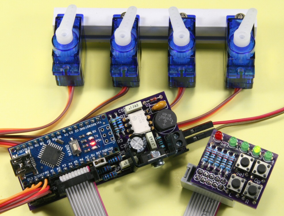
The keypad can also be used to operate the servos by hand, using the fitted pushbuttons. For convenience, as well as being able to be plugged directly into the decoder, the keypad can alternatively be connected via a ribbon cable up to 40 inches long, allowing you to see and set up your turnouts when the decoder and servos are out of sight under the layout.
Full details of the Quad Servo DCC Decoder were published in Model Railroad Hobbyist Magazine in two parts, in the February and March 2020 issues, with an accompanying set-up video available on YouTube. Copies of each part of the originally submitted article, with full constructional details, including where to obtain the printed-circuit boards and a comprehensive parts list with several sources of supply, are available from the Projects section of the Download page. The documentation here includes some unpublished details on how to set up servo operational parameters by writing directly to decoder configuration variables (CVs).
Following a number of comments from modellers who built Quad Servo DCC Decoders (QSDD), several improvements to both the software and the hardware of the original version were made. All servos can now be commanded to move simultaneously, instead of just one at a time, you can now access the decoder configuration variables (CVs) using JMRI Decoder Pro, as well as from the A-Track application featured on this site, and a new printed-circuit board is available to allow the QSDD to be powered from an external source rather than taking all the power for its servos from the DCC Command Station -

A full description of all of the improvements, together with a copy of the updated Arduino code, can be found in the Projects section of the Download page.
Thanks to the excellent efforts of José Antonio Salazar, a Spanish translation of the documentation is now also available in the Projects section of the Download page.
Gracias al excelente esfuerzo de José Antonio Salazar, una traducción al español de la documentación ahora también está disponible en la sección Projects de la página de Download.
|
|
QSDM - Quad Servo Decoder-Monitor
My brother Derek has quite a large layout, operated using an NCE DCC system, and he was keen to use a set of QSDDs to control around 80 turnouts. However, he also wanted to get feedback from each turnout to check that a sent DCC switch command had been acted upon, and that the current position of each turnout could be shown on an indicator panel or mimic diagram on a computer screen. He also has ambitions to fit block occupancy detectors to all sections of the layout track to let him see, at his central location, where all his locomotives and rolling stock are at any given time. While he could have implemented this feedback monitoring function by purchasing a set of NCE Auxiliary Input Units (AIUs), he was somewhat discouraged by the potential cost of the commercial kit, so turned to me for a cheaper DIY solution to match the proposed set of QSDDs.
For various reasons it was not possible to simply expand the functionality of the Arduino Nano module used in the existing QSDD design so I added another Arduino module, the Pro-Micro, to handle the feedback function. The result, the Quad Servo Decoder-Monitor unit, is shown below –

Full details of the Quad Servo Decoder-Monitor were published in Model Railroad Hobbyist Magazine in two parts, in the June and July 2022 issues. Copies of each part of the originally submitted article, with full constructional details, including where to obtain the printed-circuit boards and a comprehensive parts list with several sources of supply, are available from the Projects section of the Download page. The documentation here includes some unpublished details that failed to make it into the MRH Bonus Extras section.
NOTE : The software (Arduino sketch) for the Monitor part of the QSDM has been updated, and the latest version of the code can be found on the Download page.
|
|
LIM-2 - Layout Input Monitor 2 - an NCE AIU Look-Alike
In the article in Model Railroad Hobbyist Magazine on the Quad Servo Decoder-Monitor it was suggested that anyone not using servos, but needing a way to monitor sensor inputs, could build half of the QSDM to give them the equivalent of an NCE Auxiliary Input Unit. Rather than use a partially-populated QSDM printed-circuit board, a smaller board, the Layout Input Monitor, was designed for this purpose.
However, the LIM module, as presented, still required an external power supply unlike the NCE AIU which takes its power from its connection to the NCE Cab Bus. Hence, an improved version was designed, the Layout Input Monitor 2 unit, which is shown below –
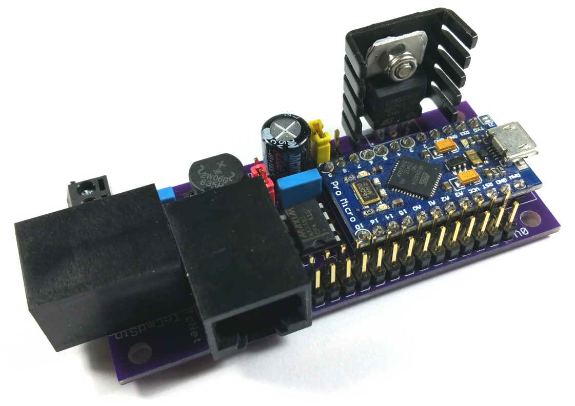
The LIM-2 module can be powered from the NCE Cab Bus, so that it becomes a drop-in replacement for an NCE AIU, or from an external power supply which can optionally be set up to provide power to the downstream section of an extended NCE Cab Bus network.
Full details of the Layout Input Monitor 2, including where to obtain the printed-circuit board, are available from the Projects section of the Download page. Since the LIM-2 uses exactly the same components as the Monitor section of the QSDM unit (apart from the printed-circuit board), please refer to the QSDM documentation for all component details and suggested sources of supply.
NOTE : The software (Arduino sketch) for the LIM-2 has been updated, and the latest version of the code can be found on the Download page.
|
|
DCC Block Occupancy Detector (1)
While various types of detector can be used to determine whether a specific track block on your layout is occupied by a locomotive or item of rolling stock, such as magnetically operated switches or infrared beam detectors, the simplest device to use with a DCC system is an inductive detector which measures, and reacts to, the electrical current being taken from the section of track designated as a block.
A typical inductive detector is the BD20, made by NCE Corporation, which, like all detectors of this type, is very simple to install and generally requires little (if any) adjustments.
When any current flows through the feeder wires to the track, as when a locomotive enters the block, this is detected by the BD20 circuitry which then effectively links its output to ground (GND). This change is passed to the input of a connected NCE Auxiliary Input Unit (AIU)) input which can subsequently be accessed by A-Track via a command sent through the NCE Command Station. A-Track can then show the block as occupied on the relevant Mimic Diagram panel.
It is possible to build a basic occupancy detector yourself, based on a cut- down version of the BD20 circuitry and using a ready-made printed-circuit board, as shown below –

Full details of the DCC Block Occupancy Detector, including where to obtain the printed-circuit board and a comprehensive parts list with several sources of supply, plus guidance on its construction, are given in the relevant description available from the Projects section of the Download page.
|
|
DCC Block Occupancy Detector (2)
The 300:1 ratio current transformer, as used in the NCE BD20 unit and the detector shown above, has recently become more difficult to source from UK and US suppliers, so this DCC block detector is designed around the ZMCT103C 1000:1 current transformer, which is readily available from a wide selection of Chinese suppliers, as well as being considerably less expensive than the 300:1 unit.
As with the previous version, you can easily build this occupancy detector for yourself, using a ready-made printed-circuit board as shown below –

Full details of this alternative DCC Block Occupancy Detector, including where to obtain the printed-circuit board and a comprehensive parts list with suggested sources of supply and guidance on its construction, are given in the relevant description available from the Projects section of the Download page.
|
|
DCC Dual Power Breaker
The purpose of a DCC power breaker is to protect the DCC command station and boosters, as well as your locomotives, decoders and rolling stock from track short-circuits or other overloads. However, if your layout is divided into a fair number of power districts each requiring its own power breaker, the relatively high cost of commercial devices can be a little daunting
A couple of basic DIY designs were published by Mike Bolton of MERG around 20 years ago but only built as prototypes, were not easily configurable, and were never proposed as finished devices. This Dual Power Breaker (DPB), developed from Mike Bolton’s ideas and shown below, is fully configurable using the onboard Arduino microcontroller, and can be built by anyone with reasonable soldering skills and the basic computer knowledge to load software into an Arduino module, for a cost of less than $50 (approx £40) –
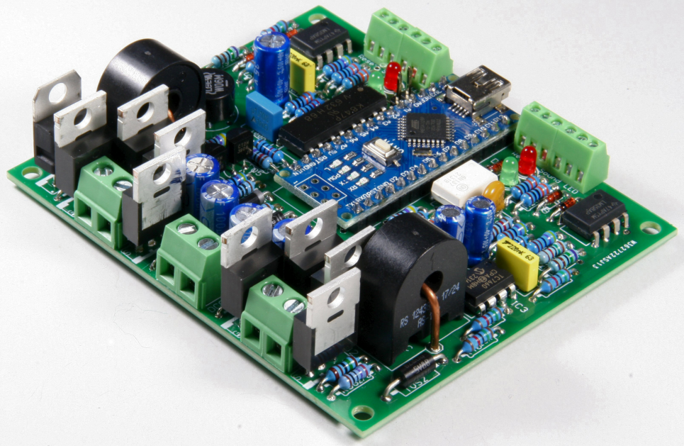
The DPB includes the switching required to cut power to both rails – not just to a single rail - and all aspects of the operation of each of the two channels can be set independently, including the current limit for each channel (power district) up to 5 amps, the delay time after the district current exceeds the set limit before power is cut off, and the subsequent delay time before the DPB tries to reconnect power to that district. After power is cut to either (or both) of the two districts you can set the DPB to attempt to reapply power automatically after the set delay - if an overload is still present, the DPB will cut off power again, and will continue to cycle through this sequence until you remove the cause of the track overload (or you cut off power to the DCC command station or booster at source). Alternatively, you can disable the auto-reconnect feature, and use a manual pushbutton on either or both channels of the DPB to reapply power to the layout.
As well as acting as a straightforward power breaker, you can also configure the DPB as an automatic reverse loop controller. In autoreverser mode both channels are used to control the DCC phase applied to the reversing loop or wye, while still providing fully-programmable over-current protection for the district represented by the loop or wye.
Full details of the Dual Power Breaker were published in Model Railroad Hobbyist Magazine in two parts, in the June and July 2025 issues. Copies of each part of the originally submitted article, with full constructional details, including where to obtain the printed-circuit boards and a comprehensive parts list with several sources of supply, are available from the Projects section of the Download page.
|
|
DCC Decoder Tester
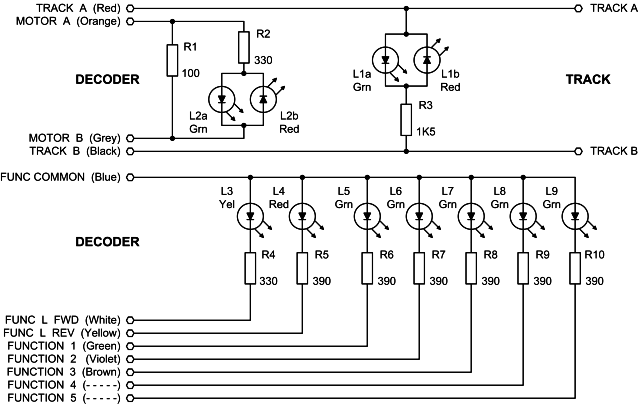
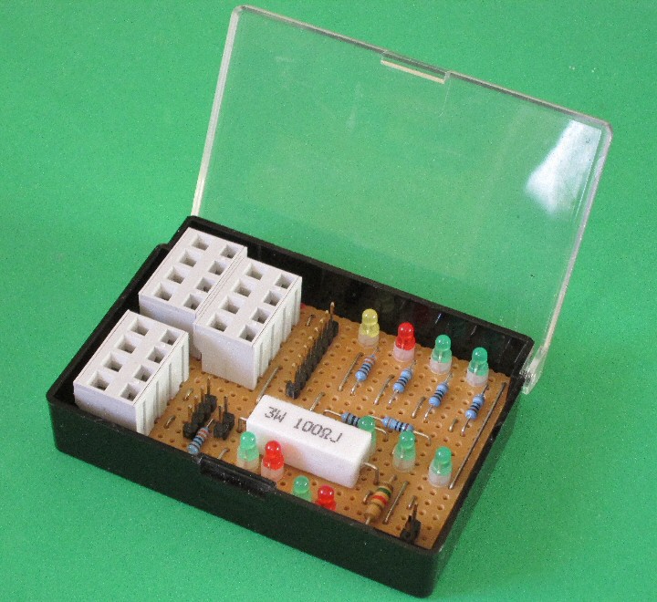
Before fitting a new DCC decoder into one of your locomotives, it makes sense to check that it is operational. This can be done with a simple Decoder Tester, shown in the schematic below, which is constructed from a set of resistors and light-emitting diodes. Any colour or type of LEDs can be used, and all resistors, with the exception of R1 are 0.25 watt rated. R1 should have a 2 watt rating as a minimum (and preferably 3 watt), since it is intended to provide a load which stands in for the locomotive motor during programming, and will have to withstand the full DCC track voltage - nominally 14 volts for HO-scale.
Connections to the track and the decoder can be made using flying leads from the Tester, terminated in miniature crocodile clips (preferably insulated to avoid inadvertent short circuits), and which are plugged on to sets of pin headers. Alternatively, you can make up wiring harnesses with appropriate sockets to take the NMRA plugs fitted to some decoders, or you can fit sets of spring or screw terminals.
To use the Decoder Tester, connect to the decoder first, then attach the final two input leads to the track, or direct to the programming outputs from your DCC Command Station. If all is well, both LEDs L1a and L1b should light when power is applied to the track by the Command Station. If only one of these LEDs is lit then it indicates that plain DC is being applied to the Tester instead of DCC power (14 volts AC). The other LEDs are driven from the outputs of the decoder under test. New decoders come with their address set to the default value of 003, so send DCC commands to this address and check that the appropriate LEDs light -
|
L2a = Motor Forward |
L5 = Function 1 |
|
L2b = Motor Reverse |
L6 = Function 2 |
|
L3 = Forward Light |
L7 = Function 3 (if present) |
|
L4 = Reverse Light |
L8 = Function 4 (if present) |
|
|
L9 = Function 5 (if present) |
A higher-quality copy of the schematic, together with a suggested layout for constructing the tester on stripboard, and photographs of a built Decoder Tester (including that shown below) is available for download.
|
|
DCC Track Monitor
This simple device shows you whether you have DCC power and signal on your track. It can either be permanently wired in place at some suitable point on the layout, or built with flying leads attached to the ends of the 470 ohm resistors, and used to check different sections of the track as required. Any convenient type of light-emitting diode can be used, but ensure that the resistors have at least a 0.25 watt rating.
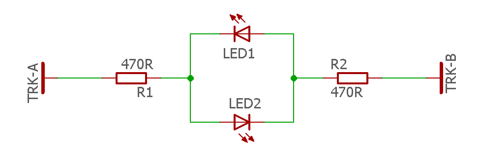
Both LEDs will light when DCC is present on the track, but only one LED will be lit, depending on polarity, if straight DC is present.
|
|
ARCC - Automatic Railroad Crossing Controller
The Automatic Railroad Crossing Controller (ARCC) is designed to operate signals and/or barriers as a train approaches a crossing, and then switch the signals off (and raise any barriers) once the end of the train is clear of the crossing.
The system works by having four infra-red light beams across the track, as shown in the diagram below. The source of each infra-red beam is a suitable LED, positioned on one side of the track, and its light is detected on the opposite side of the track by a matching phototransistor. Each of the four beams will be broken in sequence by the train as it travels along the track and over the crossing.

If a train is approaching from the left, for example, the crossing signals, etc., are activated as the front of the train (locomotive) breaks beam 'A'. The signals stay activated until the last car in the train has passed through beam 'C', and the beam is intact again. Similarly, for a train approaching from the right, the crossing signals are activated as beam 'D' is broken, and continue until the complete train has passed through beam 'B'.
It is important to appreciate that all four beams are broken as the train moves through. When travelling from left to right, breaking beam 'B' before beam 'D' effectively tells the ARCC to ignore the breaking of beam 'D' until the train has passed completely through the set of sensors, ie. until the last car has travelled beyond beam 'D'. The ARCC is then returned to its "Ready" state, where the breaking of either beam 'A' or 'D' will trigger the crossing signals. A similar sequence applies for trains travelling from right to left, where the breaking of beam 'C' stops the ARCC from re-triggering the crossing signals as soon as beam 'A' is broken.
The ARCC is designed to handle only a single track, but it is possible to handle a railroad crossing with dual tracks, by fitting a second ARCC module, with its own set of four infra-red beam sensors. The two ARCCs are coupled together so that a train running in either direction, on either track, will operate the crossing signals. If you have trains running across the crossing on both tracks simultaneously, then the first train to reach an 'outer' sensor (its own 'A' or 'D') will activate the crossing signals/barriers. These will stay active until BOTH trains are clear of their own inner sensors (the relevant 'B' or 'C').
This project has been designed so that anyone with a reasonable level of skill can assemble an ARCC (or two) for themselves. Full details of the ARCC circuitry, and suggestions for its construction on stripboard, are given in the User Guide which is available for download.
|
|
History and Features of the Original Atari Version
- a comprehensive solution to Digital Command Control
- and its evolution to Windows as an extension to the NCE Power Pro DCC System
Central, computer-based control console
|
|

Base station with support for multiple power boosters
|
|

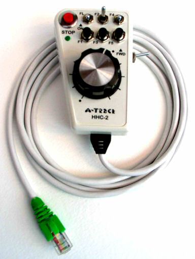
Up to 8 handheld contollers for simultaneous control of eight locomotives or consists
|
|
Compliant with NMRA DCC standards
Roster for each operating session of up to 64 locomotives
Can save all operational parameters and locomotive programming to disk
Further pictures of the various items of A-TRACK Atari hardware, together with some screenshots showing the Atari A-TRACK in operation, can be found in files on the Download page.
|
|
Summary
A-TRACK is a program originally developed for the (aged but venerable) Atari XL/XE range of computers which implements the Digital Command Control (DCC) system for the operation of model railroads. It has now been fully converted to run under any version of Windows from XP upwards.
A-TRACK supports the full range of features defined in the DCC Standards and Recommended Practices issued by the National Model Railroad Association and, with the addition of a hardware interface box (the DCC Interface Unit or DIU) to link the computer to the track, and a set of handheld controllers plugged into a network of sockets wired around your layout, will let you operate up to eight locomotives on the track at the same time. A-TRACK provides total control over a model railroad layout from your Atari computer keyboard, allowing you to set up a roster of locomotives for an operating session, allocate locos to consists and to selected handheld controllers, and even to operate all turnouts or signals from a central location. A-TRACK also incorporates full programming facilities for the decoders in the locomotives, and can save all details of the set-up for each locomotive, and the operating session, to disk for safekeeping and use at future sessions.
DCC allows the simultaneous operation of almost any number of model locomotives on complex track layouts without the use of conventional block switching, ie. each locomotive does not have to be controlled within a single section of track allocated specifically to it. The speed and direction of each locomotive can be set independently regardless of where it is on the track (a feature, naturally, which has to be used with care !). Control can also be exercised over multiple locomotives treated as a single unit (MUs or consists) and over accessories such as lighting, signalling, and points (turnouts).
The same decoders fitted to locomotives can be used to control static trackside accessories such as signals and turnouts. However, specialised accessory decoders with multiple switched outputs are normally employed for this purpose unless, of course, the accessory (a turntable or crane, for example) requires control of an electric motor.
A-TRACK and the DIU are designed to be fully compliant with NMRA Standards and to work with all makes of commercial decoder. During the period of operation, the system was successfully tested with Digitrax, Lenz, Model Rectifier, North Coast Engineering (NCE), Wangrow SystemOne (now ceased trading), and ZTC decoders.
|
|
History
In the Jan/Feb 1996 issue of Atari Classics magazine there was an appeal from an enthusiast in California, one Decker McAllister, for some help in designing an interface from an Atari 8-Bit home computer to control model railways using the Digital Command Control system - since neither he nor his colleagues had the necessary electronics or assembler code skills.
Yours truly volunteered to assist, and then spent virtually all my free time over the next four years designing first the hardware (the easy bit - I'm an electronics engineer by profession) and then the software. Because of the need to function and control locomotives in real time, the use of Basic was out of the question, and all software was written in Assembler code. The source listing stretches to over 15,000 lines of code (around 200 pages). I think it must be one of the biggest assembler programs ever written for the Atari Classic (the Atari 400/800 Operating System runs to 5800 lines). To ease operation, the software also includes a handler to allow use of a mouse - although a normal peripheral on PCs, a mouse was never supported by Atari Classic operating systems. Mice intended for either the Atari ST or the Commodore Amiga can be connected to a joystick port, although it is not possible to connect up a Serial or PS/2 mouse intended for PC use. Less than 250 lines of Assembler are required to implement a general-purpose mouse handler which can then be incorporated in the standard Atari CIO system and, hence, made accessible to any application program written in Basic or machine code.
After nearly two years of work (and considerably beyond my initial estimates) the first demonstration version of the software, was delivered to Decker and his colleague Bob DeMoss in Long Beach, California and to Charles Cole of the Cochise & Western Model Railroad Club in Sierra Vista, Arizona (co-opted into the project by Decker) just before Christmas 1997 for evaluation. Much to my relief it ran perfectly on the NTSC (USA) versions of the Atari Classic - since the software involves a lot of critical timing routines I was worried that changing to 60Hz screen frame rate from the normal PAL (UK) 50Hz rate would disrupt operations.
However, it took another full year of work to complete the design of the interface electronics, to bring them into line with the needs of the software, and then to build sets of equipment for delivery to my patient 'customers' in California and Arizona. First deliveries were made in Spring, 1999 and followed up by personal visits to the installations to set them up fully, and to iron out the inevitable teething troubles.
There was yet another year of development to produce final versions of the plug-in, walk-around handheld controllers to complete the A-TRACK system, together with associated software upgrades, but final delivery was achieved in March 2000. The largest installation, at the C&WMRRC was in continuous operation, with only minor (and easily rectified) glitches, since then right up until late 2007.
During this period of successful operation, it became clear that the limit of 64 locomotives in the A-TRACK roster was a serious limitation for club operations, being unable to accommodate all the locos belonging to the members. A-TRACK could not easily be expanded to hold a larger roster since the program already used all but a few hundred bytes of the available standard Atari 64Kbyte memory. The solution was to write a companion program, A-STILE, which allows all the club's locomotives to be handled in a single file, and selected rosters of up to 64 locos to be transferred to A-TRACK for specific operating sessions. Further details of A-STILE can be found at the end of this page.
Sadly, although Decker McAllister had seen the initial successful installation, he passed away in late 1999 following a short illness. Decker's boundless enthusiasm sustained the project throughout its lengthy development, and ensured that it does what model railroaders want - without them having to be computer experts. A-TRACK is dedicated to his memory.
|
|
Acknowledgements
Production of the software for A-TRACK would have been almost impossible without the use of the excellent SIO2PC file transfer software produced by Nick Kennedy to connect my Atari 800XL to a PC. The actual connection is made through an RS232 interface, built around a Maxim MAX232 chip, connected between the Atari SIO port and any serial port on the PC. The interface is relatively easy to construct following the clear documentation provided by Nick.
Once connected, the SIO2PC software running on the PC turns the PC into a set of 'super' Atari disk drives which can be handled under any Atari DOS system without any modifications to the Atari hardware, and without any additional software running on the Atari machine. Atari files can be stored on the PC hard drive or transferred to PC floppy disks, so you can have your complete Atari library almost instantly to hand.
Using SpartaDOS (my preferred operating system for the Atari Classic) it is possible to set up these 'super' disks on the PC with a capacity of 1MB - which was essential for the A-TRACK project where the source files amount to around 500KB and the Assembler list file alone occupies in excess of 650KB. I have to admit that files of this size are totally beyond the capabilities of any of the Atari text editors, so I actually used the PC to generate and edit all of the Assembler source code. This was then transferred to the Atari 800XL via an RS232 comms link, using a P:R: Connection and BobTerm at the Atari end to handle the communications. BobTerm, written by Bob Puff of CSS, is by far the best comms program for the Atari Classic machines and translates the PC's CR/LF ASCII characters to Atari 'End-of-Line' characters 'on the fly'. After a little more manipulation on the 800XL, the translated source file (held on an SIO2PC 'super' disk in the PC) can then be accessed by the Assembler/Editor cartridge and assembled to produce the required machine-code object program and the output list file. These are output directly to another SIO2PC 'super' disk file on the PC, since there is no way the very large files involved could be held within the 800XL's 64 KByte memory, or on a real Atari disk drive.
Although it all sounds very complex, it is relatively easy to use in practice - and very satisfying to utilise the PC as an Atari peripheral !
|
|
Future Development
Unfortunately, the Atari 8-bit machines became obsolete a long time ago with the relentless march of the IBM PC, so the future of A-TRACK lay in converting it to run on a PC under Windows. The initial intention, at least, was to retain as much of the A-TRACK hardware as possible, including the DCC Interface Unit (DIU) and the handheld controllers, so there would be no changes required to the model railroad layouts where it is currently employed.
To make things as simple as possible for myself, the software was written using Visual Basic (VB6), and the interface between the PC and the DIU (and the handheld controllers) would be via USB. Utilising USB means that the host PC must run Windows XP as a minimum, but this should not present too much of a restriction in today's PC-oriented world. A custom A-TRACK USB interface based around a Microchip PIC microcontroller - one of the range of devices which support a full-speed USB interface - was also developed as part of the initial conversion.
However, over time, it became clear that attempting to retain (and support) all of the original hardware was not the best of ideas, and a decision was made to interface A-TRACK to commercial DCC hardware. The NCE Power Pro range was selected as the easiest to handle, and development proceeded. Subsequently, a fully-operational system with hardware interface and application software was installed in August, 2008 at the Cochise & Western Model Railroad Club in Sierra Vista, Arizona without any major problems. A-TRACK features continue to be enhanced, including the ability to operate with any commercial USB-to-Serial converter unit, and the system has now been fully released through this website for the use of anyone with an NCE DCC system.
|
|
A-STILE - the Atari "A-Track Standalone Tool for Item List Editing"
This is a utility program for the Atari XL/XE range of computers which is designed to complement the A-Track software. A-Track implements the NMRA Digital Command Control (DCC) system for the operation of model railroads.
The operation of A-Track is based around the use of an Item List in which each Item contains a description and operational parameters for one of the locomotives, consists, or accessories to be controlled on the model railroad layout. The user can view the Item List and select any individual Item in order to control it or to amend its operational parameters. Item Lists are loaded from disk and, when updated, can be saved back to disk for future use. This ability is a major advantage of A-Track over current commercial DCC systems, where the operating characteristics of your locomotives are stored within the equipment itself, and there is generally no provision for maintaining a back-up copy of all the parameters.
However, each Item List may only contain a maximum of 64 Items and, although use of the editing facilities in A-Track does provide some scope for adding, deleting, and moving Items from one Item List to another, the limit of 64 Items can prove restrictive when trying to handle the full roster of locomotives in a Club, for example.
A-STILE provides a more flexible set of Item List editing facilities and the ability to handle Lists containing up to 128 Items on a standard Atari 800XL computer, 640 Items on a 130XE, and more than 1600 Items on any Atari machine with a 256KB memory extension. Item Lists can be merged, Items sorted and edited, and then saved selectively to smaller Lists which can be used with A-Track to give you, for example, the right set of Items you need for a particular operating session. A-STILE incorporates all the smart editing features that I had originally intended to incorporate in A-Track but had to leave out due to limited Atari computer memory space.
A-STILE also allows you to print a hard copy, on an attached printer, of any Item List or of the operational parameters of any selected individual Item. Although the program incorporates facilities to edit, adjust, save, and print locomotive operational parameters, it cannot program them directly into the actual locomotive decoder. For this you have to transfer the Item details to A-Track and use its on-track programming facilities through the DIU hardware.
Further details of A-STILE can be found within the User Guide which is available for download.
|
|
Copyright © JT Chamberlain 2004-2026 All rights reserved |
All trademarks and logos used in these pages are the property of their respective holders |
Page Last Updated 15 January 2026 |